
Blueprints & Wiring Diagrams
First Rough Sketch of Briefcase V.2 Layout
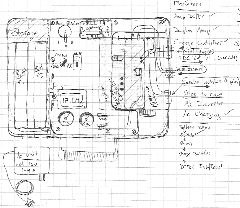
I began with a more precise version but after encountering some undesirable layouts I ripped out the page and began making a rough sketch which turned out into this slightly more refined and detailed sketch once I was able to determine how to make best use of the space within the size of the pelican case I selected. This drawing confirms that a case that has internal dimensions of roughly 12 x 8 x 5 will work to hold the required components while providing additional open space below the main access panel for additional floor-mounted components and wiring storage.
Notes:
-
1 square = ½ inch.
-
Batteries dimensions drawn are 1” wide 8000 MAH Zippy Li-Pos, the largest battery we will likely run. Enough space is present for a single 7AH led acid. The batteries were positioned vertically because a horizontal placement created dead space in my initial designs. Storage near this compartment should be adequate as designed. A pouch could also be affixed with Velcro to the lid of the case, which is component-free in this design.
-
The plexiglas component access panel is in the configuration of a C shape, which was determined to be the easiest design to cut given the overall coverage I would like to achieve.
-
The Charge Controller lies mounted to the floor of the case, offset from the Dayton Amp I have positioned above it. This offset configuration allows you to view the lights on the charge controller between the amp and the access panel and also gives the charge controller wiring room to gather between the controller and the edge of the case, keeping it close to where the external connectors will be affixed. Stacking these components made the best use of available space.
- AC Charger will be an external unit for weight savings as opposed to the heavy on-board unit in V.1. I ended up determining that it was not necessary to have a plug internal to the case as the solar input on the connector dongle would serve the same purpose.
Solar Input & Speaker Out
We need a way to input power to the case while the case is closed and sealed. The solution below will use a pair of Male/Female panel connectors that screw on and secure to the case securely. Each connector has 4 pins which could be useful for multiple solar panels or for a solar/hydro input or to use multiple charging mechanisms. 2 pins could also be ignored and used for a future use. Since only one pair is required per case, the solution could be shared.
6 pcs – Male & Female Panel Chassis Connector Kit Purchased $13 2/8/12

Note: Panel Connectors’ 4 pins are labeled with 1,2,3,4
Speaker Connector Pinout:
1 & 2 are one pair/channel, 4 & 3 are one pair/channel
(physical pin location: 1 and 4 are top, 2 & 3 are bottom)
1 & 4 are Positive
2 & 3 are Negative
Panel Connector Pinout:
1 & 2 are for Solar input
3 & 4 for variable voltage output
Polarity is the same as speaker connector configuration.
XLR to 2x RCA
One way I found that could standardize the case connections while providing a weatherproof exterior was to go with an XLR connector for the audio inputs. I have both an XLR to 1/8th inch phono wire for all standard portable music devices as well as an XLR to RCA wire for plugging directly into RCA sources from a mixing board, or from a home audio system.
A 3-pin XLR with a stereo signal can be split into left and right by wiring pin 2 of the XLR to the tip of one RCA plug, and pin 3 of the XLR to another RCA tip. Pin 1 of the XLR connects to the sleeve of both RCA plugs.


